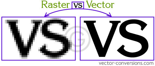
2.Computer-Aided Design

Objectives
Individual Assignment
1)Model (raster, vector, 2D, 3D, render, animate, simulate, ...) a possible final project, compress your images and videos, and post it on your class page.

Learning Outcomes
1) Evaluate and select 2D and 3D software

2D Design

Because I already have experience with 2D raster and vector-based tools through my daily work, I want to focus on the 3D modelling aspect this week. 

Mobirise

Raster Vs Vector

Basically a raster image is composed of pixels that all together create a bitmap. A vector uses math to create paths from point to point. Raster file sizes tend to be larger than vector file sizes since there is more to read in a raster.

Worth Trying Applications.

A.Vector Processing

1. Inkscape.org
2.Sketchpad
3.Layout(Advanced stuff,For ONMAX Water jet cutter)

B.Rastor Processing

1.GNU Image Manipulation Program (GIMP). (Add on BIMP you can apply a set of manipulations to an entire group of images).
2.Pixlr 
3.Photopea

Inkscape(Vector)

I downloaded Inkscape on my laptop to start modeling my project in 2D. It was pretty simple to navigate and use.

Mobirise

Trace Bitmap

Trace Bitmap

Trace Bitmap is used to convert the raster file to vector so that we can get a closed fixed boundary and feed to CNC  machine.You can find trace bit map on Objects section.Tracing is done by color based and boundary based.

Mobirise

For laser cutting a part for final project i created vector image of a part attached to rack and pinion setup which represent the time numbers.i created a rectangle with 500mm*40mm then text typed in numbers and using clone tool i incorporated box to all the numbers, therefore it look cool.

Mobirise

This is Inscape interface.I found its easy to navigate in Inkscape. I visited document properties for establishing the canvas size and or you can resize the canvas to fit in to drawing.

Other  Advanced applications tried out in Computer Controlled Cutting Week.

1.Designing Parametrically With Cuttle
2.Kiri:Moto-OnShape.
3.Vector Halftone Maker

GIMP- GNU Image Manipulation Program

It is a freely distributed program for such tasks as photo retouching, image composition and image authoring.
>Full suite of painting tools including Brush, Pencil, Airbrush, Clone, etc.
>Sub-pixel sampling for all paint tools for high quality anti-aliasing
>Extremely powerful gradient editor and blend tool
>Supports custom brushes and patterns
>Tile based memory management so image size is limited only by available disk space
>Virtually unlimited number of images open at one time

Mobirise

Using Free Select Tool

Free Select Tool

The Free Selection tool, or Lasso, lets you create a selection by drawing it with the pointer.First create the starting point clicking on your image. Then,


>>Maintaining the mouse button pressed (i.e click-and-drag), drag to draw a free hand selection. When end point comes                  superimposed on the starting point, release the mouse button to close the selection.
>>If you click on the end point, it turns accompanied by a moving cross. Then, dragging enlarges the shape.
Or release the mouse button and drag to draw a polygonal selection. When end point comes superimposed on the starting point, click to close the selection.
>>Press the Ctrl keyboard key and click on the end point: moving the mouse pointer forces moving angles to 15°; so, you can draw horizontal or vertical lines easily.
>>In both cases, double clicking on the end point closes the selection with a straight line.
In polygonal mode, this selection is a preliminary selection; ants are marching, but the small yellow circle is still present: you can copy the selection and, pressing the Backspace key, you return to the previous selection step (re-open the shape), and you can edit the selection.
>>Press Enter or double click inside the shape to validate the selection.

Mobirise

Coping the selected area and pasted in new layer in a new photo (basically he is like sitting with me) and using corp tool i adjusted the size and using color panel compensated the color to look as same scene in original photo.

Mobirise

Final Export

3D Designing

I was pretty much familiar with 3D designing in SolidWorks and fusion 360.Since I have done collab. projects in that.This part of week was to explore more tools in the same hood.
Highlight features include:
Parametric Modelling
Program tool paths for CNC machines
3D Rendering
Export STL models for the 3D Printer

Worth Trying Applications.

A.3D design

1.FreeCAD
2.Blender
3.SOLIDWORKS xDesign(Beautiful)
4.SOLIDWORKS
5.Fution 360
6.OnShape
7.Catia

B.Libraries(Publish, share, and discover 3D content on web)

1.McMaster-Carr
2.FreeCAD
3.Grabcad
4.Sketchfab
5.Tinkercad

Mobirise

Sketch

I tried to design a part for my final project.Remember, you can only sketch on a face or a plane. Since we don’t have any solids on the screen, when starting with an empty canvas, we will be picking a plane for our first sketch.
When you start your sketch, just create something close enough to your finished geometry. You will use constraints and dimensions to tie everything down afterward.

Mobirise

Extrude

From the closed path Sketch you can extrude the path do a definite length.By default, the extrude will start from the sketch plane from the profile that is selected. 

Mobirise

Pattering

Expand the SKETCH panel and select Rectangular Pattern. The RECTANGULAR PATTERN dialog box appears with the Objects selection button active. Select the cut feature in the sketch. Now, the dialog contains several more options, and manipulators appear near the sketch.The Direction/s button allows you to select an edge or work axis as a guide to control the direction of the pattern. Leave the pattern at its default directions.While you drag, the pattern begins to appear,You should now have a rectangular pattern of cut features(holes).

Mobirise

Render Options

For rendering final model First in appearance tab you should set the material and color to a required entity.then navigate to final render where you have to select the image resolution,quality and path for saving the file.

Mobirise

Final Rendered Image

Mobirise

Auto Trace

Trying out Auto Trace in Solidworks

Like Trace bitmap option in Inkscpe I imported a raster image by using sketch picture command in Solid work then i adjusted the color and contrast setting to improve the trace. finally it auto traced a optimal vector outline.

Mobirise

Extruding the  vector trace

From the trace boundary i extruded and created a 3D Model of Fab Lab logo.

I also created a plan for my final project to incorporate with  the assignments in coming week.
So that's a wrap for 2nd week Assignment.


Download design Files.Click here.


Copyright © 2021 Abel's FAB Student agreement .All rights reserved

This web page was created with Mobirise website templates